
Research
Airstreams at high altitudes contain the power to drastically increase renewable energy output, but they lie far beyond the reach of modern energy production methods. Hundreds of meters above the tips of wind turbines, these winds blow much faster, more consistently, and with less turbulence than those near the ground. Airborne Wind Energy (AWE) is an emerging field that attempts to tap into these promising airstreams by flying tethered aircraft to high altitudes, letting the pull of the craft unwind a spool of tether on the ground. This spinning spool, coupled to an electric generator, thus converts mechanical power to usable electricity as the kite ascends. And as power extraction scales with the cube of wind velocity — increasing eight-fold for every double in air speed — AWE could be a vital system in the transition to clean power to combat climate change.
While these capabilities make AWE an attractive technology, the time and energy needed to reel in a kite after every ascension cycle remains a prominent obstacle on the road to commercialization. After reaching a designated apogee, an AWE kite must typically be pulled back to a lower elevation using less energy than it produced during ascension to generate a net positive output. However, unbalanced cycles of energy production and consumption make for unappealing generation curves. This discontinuous energy production can be overcome with large smoothing capacitors or with many asynchronous kites in an AWE farm producing a net constant output, but a significant fraction of generation time is still lost during this reeling phase.
Energy efficiency for the economic viability of AWE is paramount to its success. My goal, as the lead student engineer of the Swarthmore AWE research group with Prof. Carr Everbach, is to create a flight mechanism that allows AWE kites to rapidly yet predictably descend on command. Such a kite would need to morph its shape, thereby changing its aerodynamic characteristics, to allow the wind to propel it toward the ground— the generator would then only reel in the falling tether. Inflated wings with fabric surfaces would simultaneously make the kite lighter to produce greater lift while providing rigidity similar to pressurized beams. Finally, wingtip control surfaces would be necessary to control roll stability and subsequent adverse yaw; a bridled control pod on the main tether would provide pitch control. The mechanisms that I devised to address all these concerns are: inverting airfoils.
The Inverting Airfoil
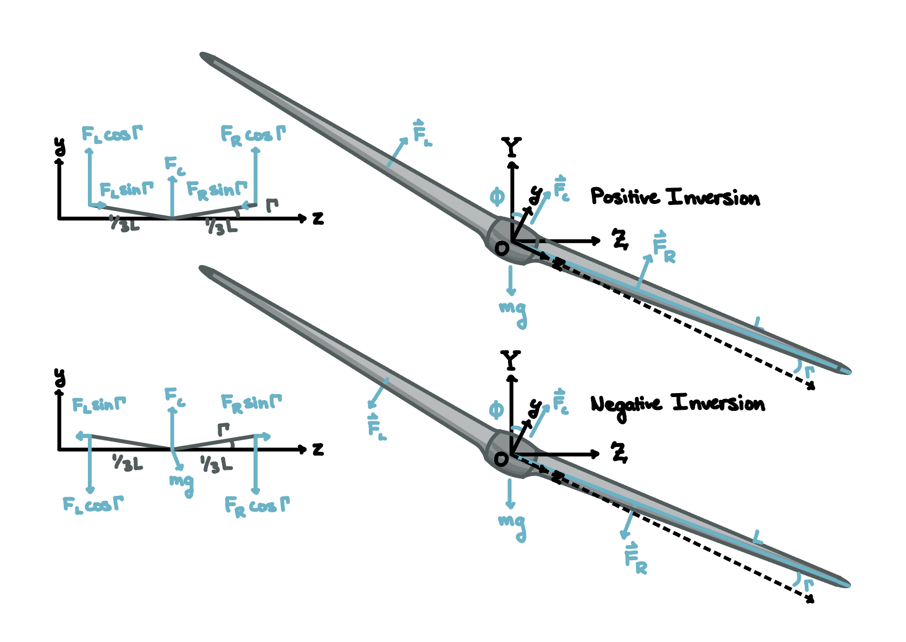
An inverting airfoil can rotate its circular leading edge to pull in a fabric surface on one airfoil side while simultaneously paying out fabric to the other. With a pressurized interior and internal fabric supports maintaining the airfoil’s outer shape, inversion effectively flips the airfoil’s camber along its chord line. In turn, these airfoils can completely reverse their direction of lift without requiring mechanically complex or heavy control surfaces typical of most aircraft wings.
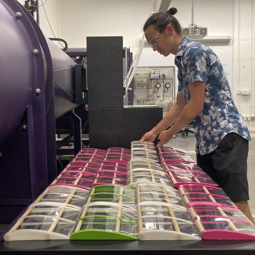
In the summer of 2021, I conducted 13 airfoil tests in the Swarthmore Wind Tunnel to determine an optimal inverting airfoil shape with a maximum lift coefficient for increased AWE generation output. NACA 4-digit airfoils showed most potential for conversion to inverting airfoils: they had generally convex shapes unlike most modern low-speed airfoils (making them feasible to inflate to), their upper and lower surfaces were defined as perpendicularly equidistant from the mean camber line (allowing a leading edge circle centered along the camber to be tangent to both surfaces), and most importantly, they were well studied for experimental validation of my own wind tunnel tests. Ultimately, a NACA 6412 airfoil with a leading edge circle centered 10% along the original mean camber proved most promising. View more.
Research Areas

Kite Structure & Stability
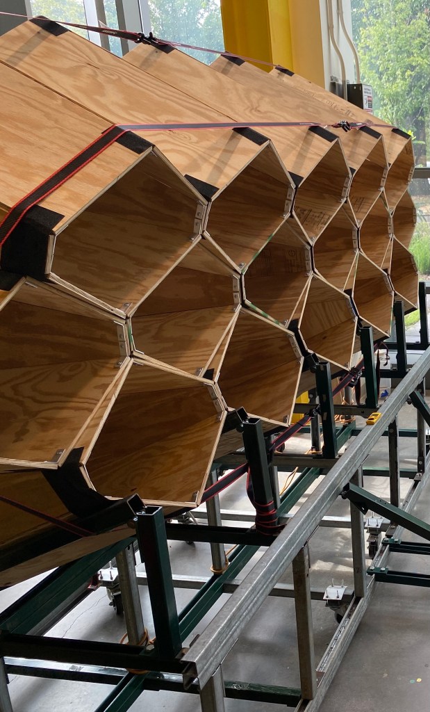
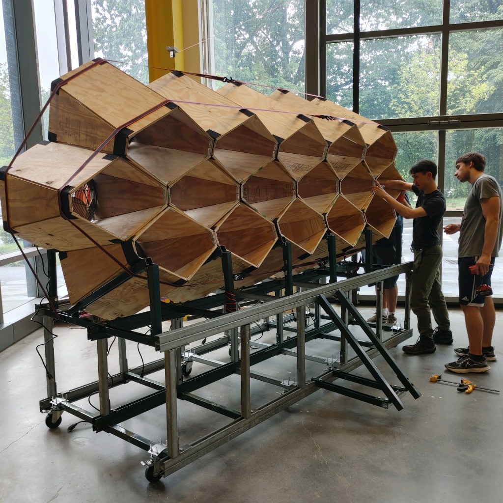
Currently my most active area of research, I am investigating how the aerodynamic stability of AWE kites can be influenced by both passive wing geometry and active control surfaces. Since airfoil inversion can be controlled independently at a wing’s root and wingtip, this mechanism can provide roll and adverse yaw control to swept wing kites as well as letting them power dive between energy cycles. These stability considerations directly dictate kite structure: three spars running along the kite’s interior wingspan will double as structural beams and driveshafts to turn the inverting airfoils at different wing sections. In the summer of 2022, I designed and led the construction of a large area wind testing platform for large scale (~3m wingspan) inverting kite tests. This fall and spring, I plan to use that testing platform to validate wing structure designs and experiment with inverting control surfaces and algorithms for active roll and adverse yaw stability. View more.
Optimization & Flight Theory
Early on in my development of inversion, I modeled the interior structure of inverting airfoils off of the classical airfoil rib and ram air kite bridle supports. However, inflated morphing airfoils act very differently from rigid ones when introduced to concentrated pressure distributions in flight. I sought to 1) numerically predict what shape the airfoil would inflate given constrained interior supports, 2) change that support arrangement for inflation to a desired airfoil shape, and 3) determine how the airfoil surfaces would deform under expected aerodynamic loads. With guidance from Professor Ganapati of Swarthmore College, I framed this problem as a simplified polygonal optimization question, where the objective function was to minimize error between an input shape and the maximized airfoil region allowed by support constraints. Ultimately, I proved that this problem was a non-convex Quadratically Constrained Quadratic Program (QCQP), and that the inflated airfoil shape would be sensitive to external loading. As such, I changed my airfoil supports to a current sheet arrangement. View more.
Wind Tunnel & Electronics
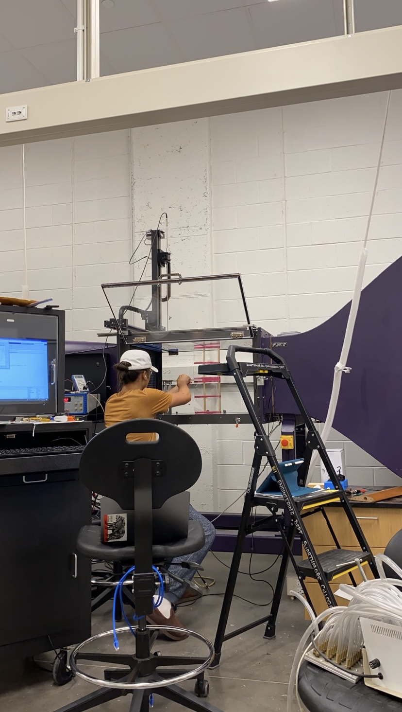
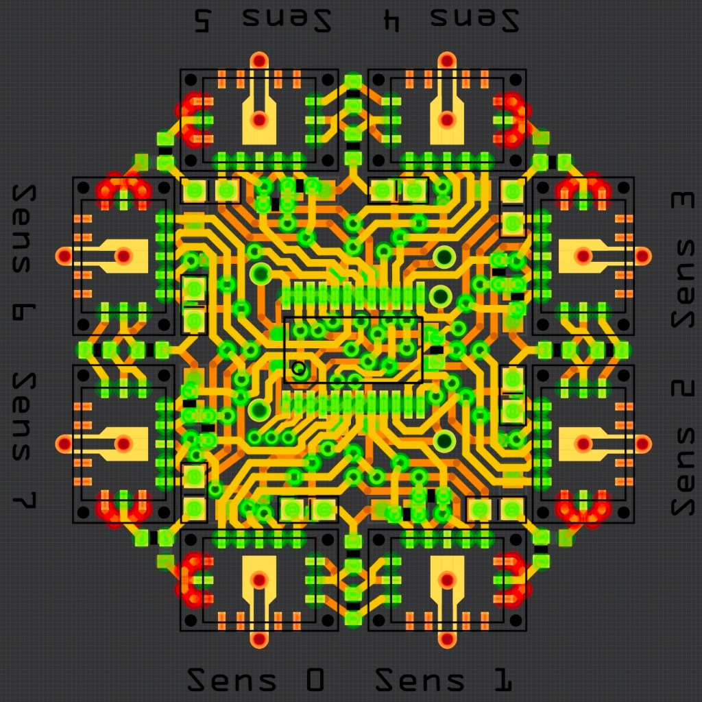
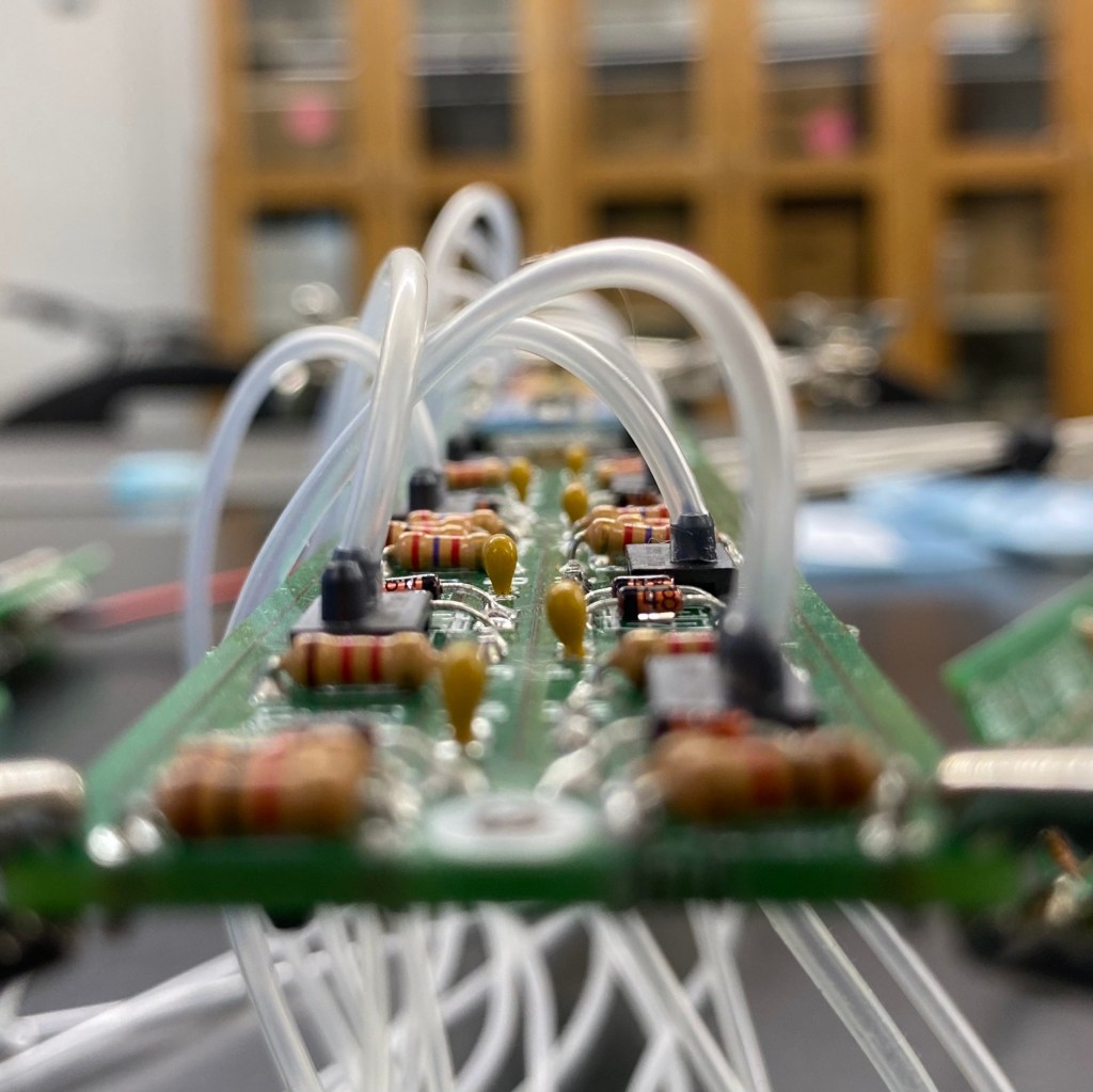
As the first student technician to service the new Swarthmore Wind Tunnel, I have contributed many MATLAB routines to the tunnel’s sensor calibration and spatial scanning programs. On top of fixing equipment and machining new strain gauge mounts, I also serve as a lab supervisor when Drexel University researchers use the tunnel for their own experiments. Since my freshman summer, I have also been developing a miniature differential pressure sensor array to compliment the tunnel’s force balance. Localized pressure distributions around the surface of a wing are a key factor in determining the wing’s aerodynamic characteristics, so fitting such a sensor array inside a wing would benefit future wind tunnel research. My first working array fit 6 sensors on a 5in2 printed circuit board (PCB); my second major redesign packed 24 sensors onto an 10in2 PCB; my current iteration squeezes 16 sensors into a 1.6in2 area. This latest PCB also houses dozens of other surface mount devices, multiplexers, and indicator LEDs. View more.
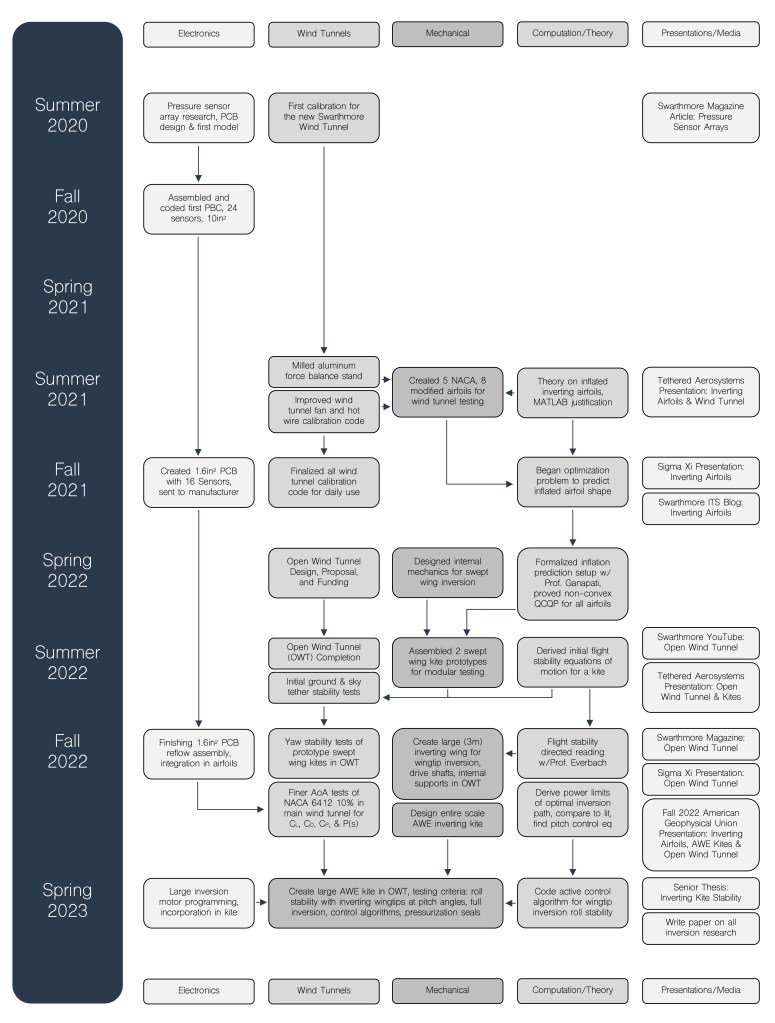
Research Flowchart
Research In The News
joshvandervelde@gmail.com | 315-261-8478
